1. People.
2. Money, and…
3. Time.
People:
Usually, it is not difficult to get together enough motivated people to make up a FS team. In fact, sometimes there are too many volunteers.
Money:
This is more difficult to come by, but sponsors are out there and finding them can take time.
Time:
This is the difficult one. You can always get more people and more money, but you cannot get more time. In this COVID limited season, time is even more precious, so the intent of this article is to suggest how new or inexperienced teams can get to their event despite the constraints of less money and less time. This will be a lesson in pragmatic engineering!
KISS PRINCIPLE:
The theme that will be followed in this presentation is the ‘Kiss principle’.
“Keep It Simple, Stupid” The acronym was reportedly coined by Kelly Johnson, lead engineer at the Lockheed Skunk Works, a story for another time. If you want a more sophisticated principle to follow, Leonardo DaVinci said “Simplicity is the ultimate sophistication”.
PRAGMATISM:
COVID has changed the rules. It has stolen our irreplaceable time, so we must make some hard decisions to recover some of this lost time. To start with, do not waste time designing or making any component you already own or can buy.
This includes such things as steering wheels, seats, an impact attenuator, road wheels etc.
It also means you do not incorporate anything into the design that is unnecessary or that complicates the project. This includes such things as suspension bellcranks and operating rods, electric or pneumatic shifters, turbochargers and aero packages, unless the team already has these features to carry over from a previous car.
DESIGN DECISIONS
1) Powertrain
In keeping with the KISS principle, some attractive design dreams must be put off for another year when more time will be available.
This means the complexity of an EV should be avoided unless the entire powertrain is already available to your team from a previous car.
An IC powertrain, unless already available to the team, should be a monocylinder engine of whatever capacity is available. Availability of the engine, parts and service support should be the prime decision decider. There is no ‘best engine’!
A monocylinder choice means much less time needs to be devoted to the development of the intake and exhaust systems. Suitable engines can be sourced from most motorcycle manufacturers.
2) Chassis
A spaceframe chassis is easier (quicker!) to make and easier to modify if necessary than a composite or sheet metal monocoque structure.
I suggest the chassis should be made of square section tubing where possible (Main Roll Hoop and supports must be round tube). Although square tube is about 27% heavier than round tube of the same length and thickness, square tube has time saving benefits that will outweigh any small increase in the finished vehicle weight.
- Square (and rectangular) tube is easily cut and mitered to make safe structural joints without the need for close-fitting ‘fish mouth’ joints needed with round tube structures. This will save significant time constructing the chassis.
- Square tube resists bending better than round tube, so small offsets at nodes will affect total stiffness to a slightly lesser degree. Square tube eases the fitment of panels, which will add stiffness whilst fulfilling the need for compulsory bodywork.
- It is easier to incorporate tabs and brackets into a square tube structure, thus maintaining good load paths.
- It is easier to properly repair damage in a square tube structure.
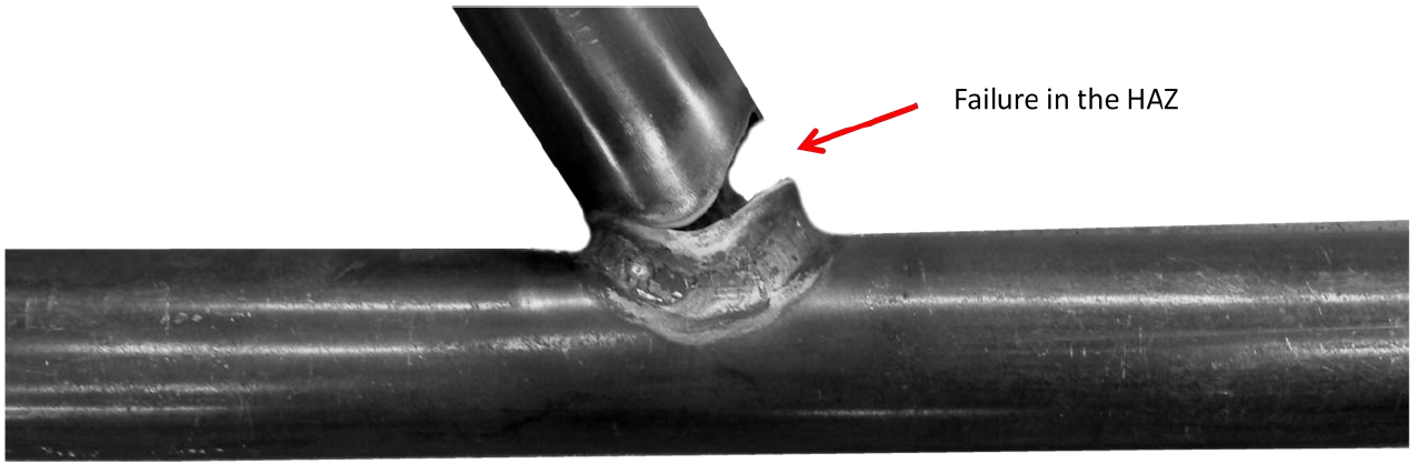
If alloy steel (ie, ‘chrome-moly’) steel tube is used, the team should remember that welded joints will need to be ‘normalised’ to avoid cracking in the heat affected zone at stressed joints.
3) Suspension and Steering
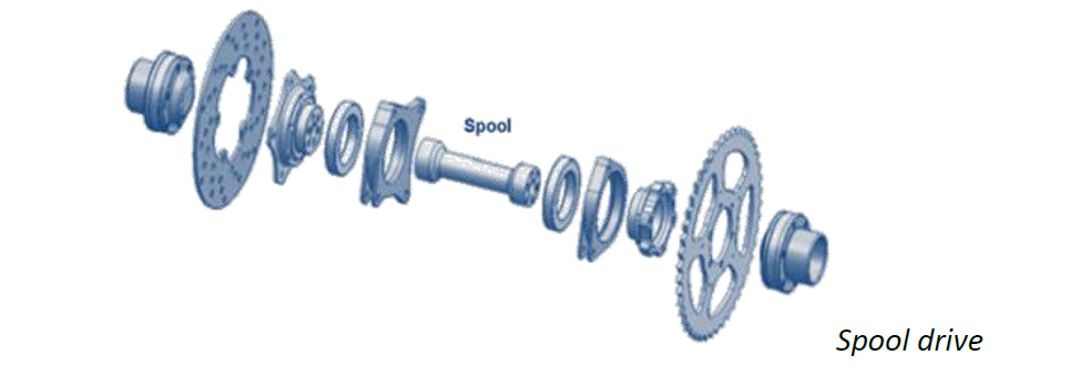
Suspension design should be as simple as possible with few moving parts. A good model is what was used when real racecars used spaceframe chassis, see the picture.
This means there is no need for push-rods or pull-rods and their associated bellcranks. This should reduce the number of nodes needed in the chassis to ensure adequate stiffness and so make for a simpler chassis design.
Note, I am not suggesting that you abandon kinematic design for the suspension and steering systems, just that the actual mechanics should be simplified in the interests of cost and time savings.
Remember, the intent of suspension is to keep the tyre happy at the contact patch whilst generating the expected traction. A good guide to suspension design is to remember the following points.
- The most important adjustments at a circuit are camber and toe.
- Good steering and suspension design allows adjustment of one parameter without upsetting another, i.e.; a camber adjustment does not change the toe setting. Adjustments should be easy to understand and make so people won’t screw up.
Some approximate (≈) starting points for suitable suspension and steering settings are as follows…
Front Camber ≈ - 2°
Front Camber Gain ≈ -1° per 25mm of wheel travel in bump
Front toe setting ≈ 3mm toe OUT.
Front Caster setting ≈ 3° - 6° (Use the upper figure if a spool drive is used)
Front scrub radius ≈ 50mm – 100mm (Use the higher settings with a spool drive)
Front SAI (KPI) ≈ As little as practical.
Ackermann ≈ 100% to 150% (higher setting with a spool drive).
Rear Camber ≈ -1°
Rear Camber Gain ≈ -1° per 25mm of wheel travel in bump.
Rear toe setting ≈ 3mm toe IN.
Rear scrub radius ≈ As little as possible.
Roll/Bump steer – FRONT - as little as possible, REAR - NIL.
Roll Axis ≈ A little above ground level when static.
4) Major Design Errors (aka “Mortal Sins”)
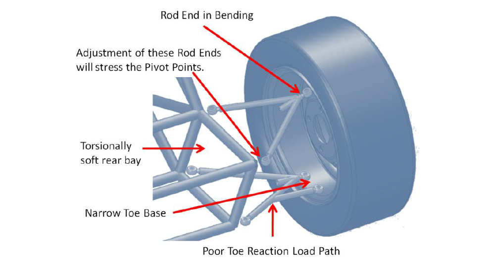
- REIB. Short for ‘Rod Ends in Bending’, that is, loading the threaded shank of a rod end or clevis in bending. The stress riser at the thread root will cause a failure unless the thread diameter is way oversize. The judges hate this and will penalize it in the Design event.
- Excessive toe compliance, especially at the rear of the car.
- This is usually caused by the toe reaction base being too narrow or the load path reaction is poor.
- Feeding a force into an unsupported tube (often the rear toe reaction load path.) It is most commonly seen where teams mount a bellcrank pivot point on an unsupported tube, thus ignoring the vector produced when the suspension forces change direction. Forces always want to travel in a straight line until they reach their reaction point (usually a node in the chassis).
- Poor ergonomics. Driving a Formula Student car is hard work! If the driver is tired or cramped, he cannot drive even the best car effectively. Often, the culprit is simply the steering wheel is too small!
All other things being equal…
1. The car with the lowest weight will win!
2. The car with the lowest C/G will win!
3. The car with the lowest PMI (Polar Moment of Inertia) will win!
So, design to reduce the weight, lower the weight and centralize the weight. The best way to remove weight from the car is not to add it in the first place! If something does not need to be on the car, then leave it off!
Something NOT on the car…
- Costs nothing.
- Weighs nothing, and
- Cannot break.
If you follow these recommendations, particularly the KISS Principle, you should be able to build, test and present a workmanlike car at Formula Student, despite the handicaps imposed by the COVID pandemic.
You can email me if needed for any further advice at jpatc@hotmail.com. Please identify yourself and your team.